▶ C'mon over to https://realpars.com/ where you can learn PLC programming faster and easier than you ever thought possible!
=============================
▶ Check out the full blog post over at
https://realpars.com/main-switch/
=============================
We’ve already covered some of the important aspects of a control panel, but some might say that what we’re going to cover today is the most important of all.
The Main Switch is the one part of a control panel which has a large impact on progressing a project.
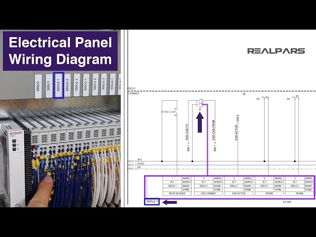
When we look at the panel from the outside, one of the first things we see is something labeled the Main Switch sometimes called an isolator.
What it does essentially is applying or disconnecting the control panel from the power source.
The control panel that we have is powered by a 3 phase supply, which is rated at 415 Volt AC.
This, in turn, can be used within the panel to power single-phase devices, or 230 Volt AC by using 1 phase of the 3 phase supply.
We can also use transformers to convert AC voltage to DC voltage to power our 24 Volt and 12 Volt devices we briefly covered in the Control Panel overview video.
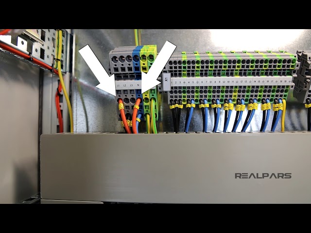
We usually designate the 3 phases with the following labeling system; L1, L2, and L3 are the 3 phases of the supply. N is the neutral wire. The neutral wires’ purpose is to provide a path back to electrical ground to complete the circuit.
When we put the main switch in the 0 position, it indicates that the isolator is in the OFF position, and it will disconnect the power flow to the control panel.
When we put the main switch in the 1 position, it indicates that the isolator is in the ON position, and it will enable the power to flow to the control panel.
On the back of the door, this switch has wires connected to the terminals on the switch. These are connected to the main power coming into the cabinet labeled L1, L2, L3, and N also.
The other side of the switch connects to the distribution unit. One of the phases goes to power the power supplies.
The input to the power supplies can be 100-240 Volt AC. Inside, these power supplies transform the AC signal into a DC voltage output. This DC power can then be used for devices in the control panel, or for devices out in the field too!
The rest of the 3 phase power goes into the terminal block and can be used to power the devices that work with 3 phase power.
When we install this control panel in the field, the 3 phase supply will be connected to the top of terminals. Then through the trunking, they are going to be connected to the top of the main switch.
We have the 3 phase supply connected on the bottom and the devices can be connected to the top of the terminal blocks.
If we put the main switch to the 0, the incoming 3 phase supply power will be disconnected, and that shuts down the whole control panel, including all of the devices that work with 24 Volt DC and 12 Volt DC, and also the devices that work with 3 phase power.
=============================
If you want to get in contact with Pro-control, you can check out their website over at https://www.pro-control.nl/
=============================
Missed our previous video, “What does an Orange Wire do in an Electrical Control Panel?”, Watch it here:
https://realpars.com/orange-wire-control-panel/
=============================
Missed our most recent videos? Watch them here:
https://realpars.com/orange-wire-control-panelhttps://realpars.com/control-panel-cooling-system/https://realpars.com/electrical-control-panel-basics/
=============================
To stay up to date with our last videos and more lessons, make sure to subscribe to this YouTube channel:
http://goo.gl/Y6DRiN
=============================
TWEET THIS VIDEO https://ctt.ac/n_0w8
=============================
Like us on Facebook: https://www.facebook.com/therealpars/
Follow us on Twitter: https://twitter.com/realpars
Follow us on LinkedIn https://www.linkedin.com/company/realpars
Follow us on Instagram https://www.instagram.com/realparsdotcom/
#RealPars #Automation #Main_switch


71 Comments